This in-depth article will explain everything you need to know about designing parts so that they can be 3D printed using Selective laser Sintering (SLS).
< Back to articles
Selective laser sintering (SLS) is one of the main types of additive manufacturing (AM) available to engineers and designers. Like other forms of 3D printing, SLS technology excels at producing complex geometries, but unlike others, it is also a scalable method of mass producing functional products. Crucially, unlike most other additive manufacturing processes, no support structures are required for the SLS 3D printing process.
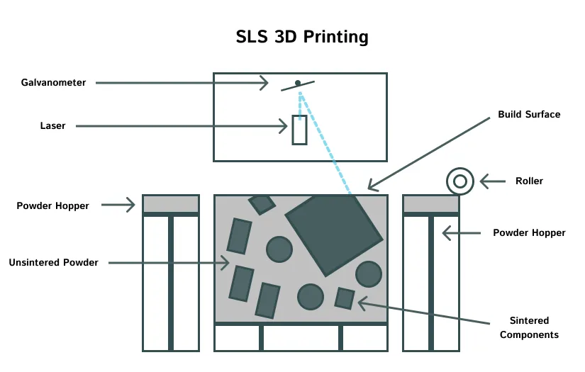
The material required for SLS 3D printing is a powder, unlike FDM or SLA, which use filaments and resins respectively. The process starts when a quantity of fine polymer powder is spread in a thin layer inside the SLS machine using rotating rollers. The temperature inside the machine is kept just below the melting point of the material being used. A laser is then focused onto the surface of the powder, and moves across the build area, in a pattern corresponding to the cross-section of the part/s being manufactured. The powder is heated, and partially melts, where the laser light hits. These areas 'sinter', meaning that the individual powder grains join to one another, and become a continuous solid when they cool.
Once one layer is complete, a new layer of powder is deposited on top of the previous one, and the process repeats. The powder, both sintered and unsintered, is then very gradually cooled to room temperature, before the finished parts are extracted. A certain percentage of the unsintered powder can then be recovered, and mixed with fresh powder, ready for the next build. The extracted parts are then post-processed, to remove any unsintered powder, and improve the surface finish.
As the unsintered powder surrounds the parts being built at all times during the process, SLS parts don't require support structures. This gives the designer greater freedoms than many other manufacturing processes offer. The most common layer thickness is 0.1mm (100 microns).
SLS was pretty much a standalone technology until 2016, when Hewlett-Packard launched Multi-Jet Fusion (MJF) technology. This proprietary technology is very similar to SLS, but uses a slightly different approach. Instead of using a laser to sinter the powder, MJF machines spray a fusing agent onto the surface of the powder, and then use an infrared heater to sinter only the powder coated with fusing agent.
For most purposes, SLS and MJF are interchangeable, and the design approach is essentially identical. Click here to read more about the differences between MJF and SLS.
Much like FDM 3D printing, SLS 3D printed parts are anisotropic. The strength of parts in the plane that the layers were sintered in (XY plane) is far greater than in the direction between the layers (Z axis).
If SLS parts are but into tension in the z-axis, relative to how they were built, then parts can delaminate - which is where the layers making up the object rip apart from one another. Experienced 3D printing service bureaus will carefully take this into account when deciding on the proper part orientation in the build chamber.
The best way to ensure that your parts are as strong as possible, and unlikely to break, is to ensure that any forces the part must resist, act only along the plane of each 'slice', and not through them. More advice on this is included in our 3D printing orientation article. If building parts that were designed generatively, make sure your study parameters take into account anisotropism, as the complex geometries that are produced using these techniques can otherwise be prone to failure.
By far the most common material used for SLS is nylon, or polyamide. This is most often in the form of nylon 12, but nylon 11, and nylon 6 is also available. SLS nylon exhibits many desirable properties for engineering components, such as high thermal stability, durability, impact resistance and chemical resistance. This is the only SLS material we currently offer at Printpool.

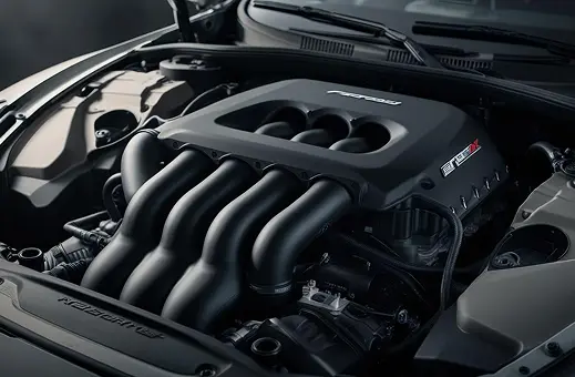
Other materials are available also, but are harder to print with, and build failures are more common. Carbon filled polyamide, and glass filled polyamide are popular, and can be used for producing functional products for the automotive and aerospace industry, as they are very rigid, with even better temperature resistance than SLS nylon. Thermoplastic Polyurethane (TPU) is also a popular choice for making flexible components.
SLS 3D printing has been around for quite a long time. The first patents were registered in 1988, and for a long time 3D Systems and EOS dominated the market, and indeed are still major players. These companies produce machines that can be regarded as industrial workhorses, and they are frequently used by service bureaus, and larger companies. They are reliable, and have large build volumes, and produce parts of excellent quality.
In more recent years, a number of companies have marketed smaller, 'desktop' SLS 3D printers. Despite their name, these are still very much professional level machines, and most require the same PPE, compressed nitrogen gas supply, and expertise as their larger cousins. The main difference is in price, speed, and size. Desktop SLS has a smaller build volume, and slower print speed - but can cost as little as 10% of the price.
The latest development in SLS technology is known as Fine Detail Resolution (FDR) 3D printing. This is a technology developed by EOS, and is capable of producing parts with extremely detailed features, and very thin wall thickness.
Despite the relative freedom offered by selective laser sintering, there are still various considerations and design guidelines that apply.
One of the most important defects to be aware of when designing parts for SLS 3D printing is warping. Like FDM 3D printing, the SLS printing process uses a lot of heat. Sometimes certain areas of a part can cool faster, and therefore contract faster, than others after the print has finished. This differential cooling can cause stresses to develop, which make large flat surfaces twist, curl and warp.
To prevent parts from warping, it is good practice to design your parts so that they have a consistent wall thickness. This will ensure an even cooling rate once the print has finished. Avoid large flat surfaces where possible, and consider adding ribs to resist the warping effect.
Boxy shapes, such as electronics enclosures, should be oriented in the build volume so that the major axes of the design don't line up with the axes of the build chamber. Generally aligning major flat surfaces at an angle of 45° is a good best practice.
Some service providers (including us) recommend that very thick areas of your design should be shelled (made into hollow parts) to resist warping. Bear in mind that escape holes should be added in these instances if possible, to reduce the cost of the component.
It is relatively simple to shell or hollow parts using CAD software. The chosen thickness should match the thickness of the rest of your design where possible, but usually around 3-4mm is ideal.
It is important to add escape holes to your design, so that the unsintered powder can be removed. Powder removal is made much easier if you add multiple escape holes of 4mm diameter or greater, allowing access into the hollow void. 3D printing technicians can then shake the excess powder out of the escape holes as a post-processing step.
If you require a high surface finish on the inside of hollow parts, a few escape holes may not be sufficient. Consider designing features that will allow 3D print technicians to access the inside surfaces, or even perhaps consider another technology such as SLA 3D printing that can achieve a superior surface finish without post-processing.
Threaded SLS parts can be made in a number of different ways. Larger diameter threaded holes (M5 or larger) can sometimes be printed directly, but for most applications, it is better to use a tap and die set to cut threads as a post-processing step.

Better still is to use heat-set threaded inserts, which can be easily installed into a pilot hole designed into the part. These are far stronger than either printed or cut threads, as they are made of metal.
Just like with injection moulded parts, it is possible to use SLS 3D printing to make living hinges. These are commonly used in packaging, boxes and enclosures - often combined with snap-fit hinges. Nylon 12 is an ideal material for this purpose.
Living hinges for SLS 3D printing should be a little longer, and thicker than those you may have designed for injection moulding. They should be at least 5mm long, and generally around 0.4-0.6mm thick. Use multiple small sections to experiment with different geometries for your particular applications.
Functional living hinges can be annealed after the printing process has finishes, to make them more resilient. This involves heating them to above the glass transition temperature of the material, to let the polymer chains relax. Hinges treated in this manner will withstand many more cycles before failing.
As with all parts, 3D printed or otherwise, sharp edges, corners and notches can act as stress raisers. This is particularly important in 3D printing however, as these stress raisers can cause encourage parts to delaminate when positioned in certain locations.
No support structure is needed with the SLS process, and so any and all sharp edges and corners should be filleted for the maximum strength.
Like other forms of AM, much of the SLS 3D printing effort comes in the post processing stages. The post processing SLS parts can be automated very effectively however, as there is no support structure to remove. This section will explain some of the most common options, so that you can select the best ones for your application.
This step is mandatory, and will happen to all orders. When SLS components are removed from the printer, they are completely encased in a block, or 'cake', of unsintered powder. Much like a lucky dip at a fairground, print technicians sieve through the unsintered powder in search of the solid components that lie within.

This step is sometimes automated, using machines that rotate and bounce the powder cake around, and let the unsintered powder fall through a sieve, leaving the components.
Various brushes are often used to scrub unsintered powder from the parts. This is generally done in a post processing station of some kind or another, which must have extraction, to avoid the cloud of powder from billowing into the room. Operators must also wear appropriate PPE, such as a facemask and gloves, to avoid inhaling the powder.
This is an optional step. Once the parts are clean, dry and free of powder, further post processing to improve surface quality is possible. These steps are mutually exclusive - only one of the three can be performed on a given part.
Polishing is a very simple step, but produces excellent results. Parts are placed in a rotating bath of water, and a specific grade of polishing media. After a couple of hours, parts have significantly reduced surface roughness. Sharp edges may be slightly rounded by the process however, and delicate features, engraved details and thin walls may be compromised.
Shot-peening is an alternative method of smoothing parts, that doesn't compromise your design's geometry. Millions of tiny ceramic or plastic shot pellets are fired at the part using compressed air, which impinges on the part surface, causing tiny and imperceptible dents. The overall effect of this is an improved surface, without the loss of crisp details that polishing can create. Again, fragile features may be damaged, and interior features may not be accessible.
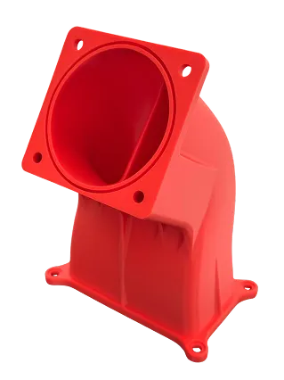
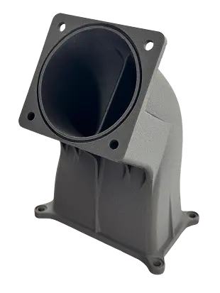
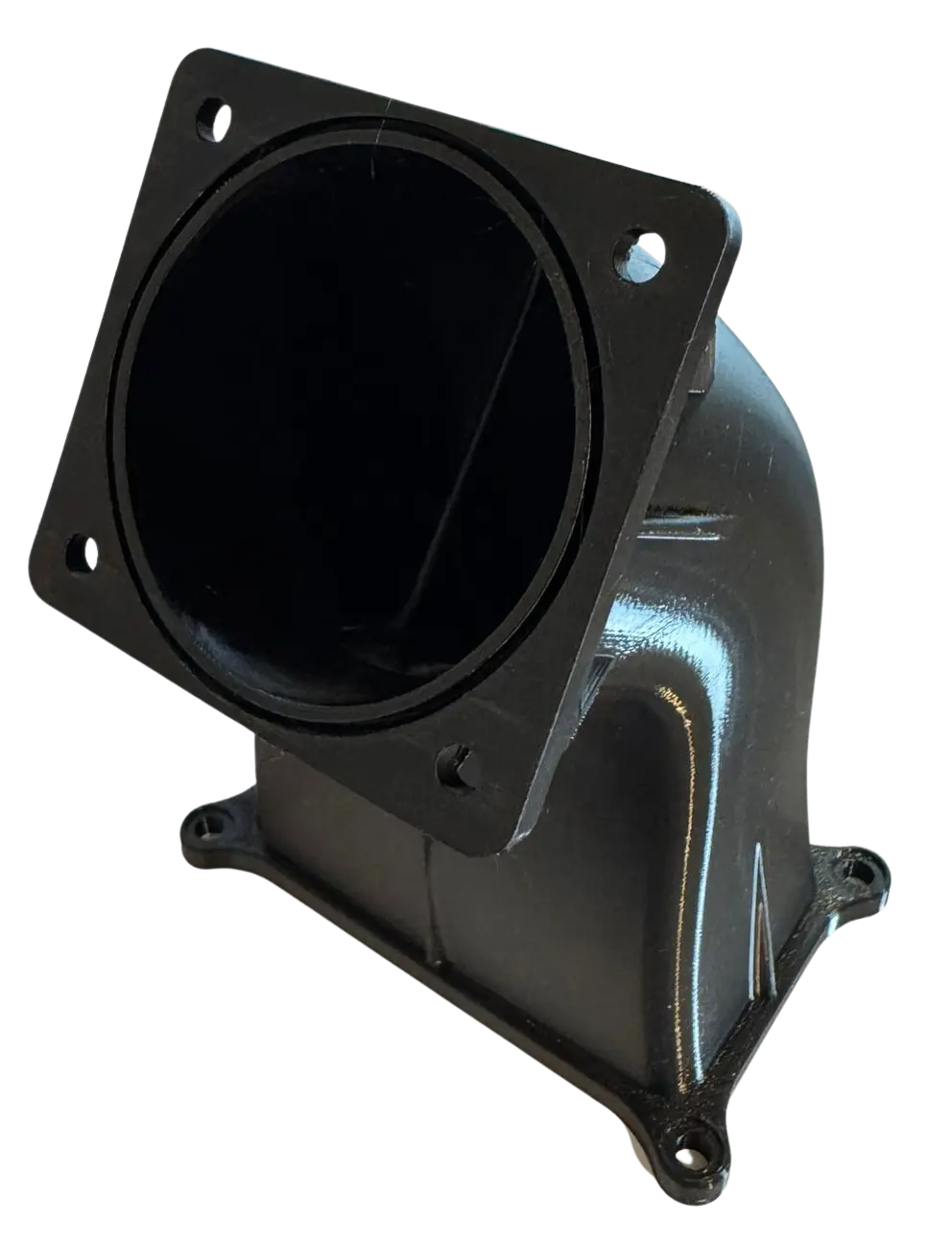
Due to the porous nature of SLS nylon, dyeing parts is a highly effective way to bring some colour to your designs. SLS parts can be dyed in a range of different colours, but generally black is the most popular! The dye will penetrate a few millimetres into the surface, unlike paint, and is very durable.
Another, more classic alternative, is painting. As with any component made by 3D printing, a wide range of different paints, and other coatings can be used effectively. This is a highly manual process however, unlike dyeing, and so can be significantly more expensive.
Without a good understanding of exactly what your part must do, it is impossible to design an effective component. Most times the clearer you are at this stage, and the better defined the use case is, the better the final part will be.
There are a few different SLS 3D printing materials available. Good 3D printing providers will work with you to identify the best material for your application.
Sometimes it may turn out that the best material for you is actually an FDM 3D printing filament, or SLA resin. That's ok! It's better to know that at this stage than when you've already committed to designing for SLS 3D printing.
Traditional manufacturing has influences engineering designers a lot. You learn early on to produce cost effective components by making as few cuts into a solid billet of material as possible. This keeps manufacturing costs down, but only when using traditional manufacturing.
That is exactly what shouldn't be done here. The best way to design for an additive manufacturing process is to focus on designing in functionality first, and then add material slowly and reluctantly afterwards as required.
Using the example of a hole, use CAD to model the correct size and depth. Only add the amount of material around the hole needed to make it practical and strong enough to work (maybe 5-15mm, depending on material). Leave this feature floating in free space as a separate body, and then move onto the next one - perhaps a complex surface that interfaces with the user's hand, or a battery housing. Again, use the minimum of material.
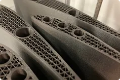
At this point you'll have a number of free floating bodies. The goal is now to connect them into a single component, using as little material as possible. For SLS 3D printing, we often use generative design techniques, and/or lattice structures at this point - to take advantage of the design freedom that is possible.

Selective laser sintering is particularly well suited to complexity, but beware making lattice structures too fine. An operator must still be able remove the unsintered powder material from in-between the various unit cells. We recommend a cell size of 3mm as the lower limit.
You'll probably have a blocky part now, that's just about in one piece. Further refine your design, by removing any material that doesn't fulfil a specific purpose or function.
By this point in the design process you should have a good idea of what orientation is best for your design. Look at the angles between surfaces and the location of key features. Think about what direction forces are likely to act, and how the part should be built with that in mind. Remember that hole orientation is particularly important.
Some final design changes may be necessary to ensure that the specific printer you use, or your service provider uses, is happy with the size of all your features. Once this is complete you can export your design for additive manufacturing.
These guidelines are the ones we use to evaluate the feasibility of powder 3D printing designs. Each service provider will have their own versions of these guidelines, but most are fairly similar.

The maximum part size we can print in one piece is currently 165mm x 165mm x 300mm. Other 3D printing providers, and machines, will vary. More expensive machines generally have a higher print speed which can make a big difference on large jobs.

We recommend a minimum hole diameter of 1mm if orientated vertically, and 1.5mm if orientated horizontally. Powder removal can be difficult with deep holes, so keep this in mind.

Any overhang is possible with SLS 3D printing.

We have a suggested minimum wall thickness of 1.5mm. Where a vertical wall connects to many other walls, you may be able to get away with slightly thinner designs, as each one is better supported. 1mm is the absolute limit however. A consistent wall thickness is highly desirable.

Embossed writing or logos should be a minimum of 1.2mm thick, with at least 0.8mm of depth (or height) in order to be readable. A minimum suggested text size would be around 3mm. Wherever possible, embossed or engraved text should ideally be facing away from the build plate, on the top layer of your component. Other post processing operations may be required to highlight and clarify small text.

Any length of bridge is possible with SLS 3D printing.

Forgetting to give mating parts the proper minimum clearance is a common problem in design for additive manufacturing (DfAM). For mating assembly parts, we recommend a minimum clearance of 0.15mm is designed in. This will produce a interference fit. For a looser, sliding fit, use 0.2mm or 0.3mm. Parts designed to mate together with components fully assembled should print in a similar orientation, so that any warping affects both parts similarly.

To avoid fragile features either not building, or immediately breaking, we recommend a general minimum feature size of around 1.5mm. Check complex geometries carefully to ensure that no areas are thinner than this, as they may break during post processing.
Unit 3, Stanley Court
Richard Jones Road,
Witney OX29 0TB
01865 597786
enquiries@printpool.co.uk


© Copyright 2025 Printpool Additive Manufacturing Ltd. All Rights Reserved.
Company number 12732758
VAT number GB354866659


.png)